Road Blocker

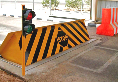
Hydraulic Rising Road Blockers

General Description
Road blockers are designed especially for entrance points which have a threat of vehicle attack or for the ones that have high security requirements. If there is a threat of vehicle attack in addition to the control of vehicle access in high security applications, hydraulic road blockers are the unique solution and the most secure systems. Even though the attack is from high tonnage vehicles with high speeds, it’s not possible for the vehicle to keep on moving because of the damage given to front, wheels and the bottom of the vehicle. road blockers are designed to K12 standards. Finite element model analyses are available upon request. Drive unit is electro-hydraulic, but in case of power failure road blocker can be lowered or lifted manually with the help of hand pump. Or by using hydraulic accumulator, it is a pressure storage reservoir in which a non-compressible hydraulic fluid is held under pressure by an external source. It used for 3 cycle raise/lower. Typical raise/lower time is 3 seconds. In case of emergency, raise/lower time can be as low as 1.5 seconds. With the help of PLC (programmable logic control), raise/lower function can be achieved by every kind of card readers, biometric readers like fingerprint or hand shape, radio control, on/off key switch etc. Besides, safety accessories like photocells, inductive loop detectors, flashing lights or red/green traffic lights can be integrated to the system very easily. Typical weight of a road blocker is 2-2.5 tons (depending on road blocker type).

Steel Construction
Main mechanical elements forming the construction are heavy duty 10-12 mm top plate and the frame consisting of 100x100 box, 200x75mm U and 100x10 mm metal sheet & plate. This sophisticated mechanical design enables the road blocker to withstand minimum 22 tons of axle loads, besides, in case of crash, linkage bars transmit the impact directly to the foundation, therefore help to protect the steel structure. Cushioned cylinders power the road blocker up as they pivot on multi- sealed bearings. Steel construction is either sand blasted and hot dip galvanized (upon request) and 3 layer primary coated in order to prevent rusting. Additionally the parts which stand above the ground level are yellow-black painted

Hydraulic Power Unit & Control Electronics
All the hydraulic components are tested at 250 bars although normal operating pressure is around 75-100 bars. Manuel hand pump is standard in all HRR series, therefore in case of power failure it is possible to raise and lower the blockers by manual hand pump. Coolers or heaters are can be integrated to the hydraulic power unit. Control electronics utilized in hydraulic road blocker is PLC controlled. Two keyboards with emergency stop are standard; one desktop, other being integrated in the hydraulic power unit. Motor is driven by a contactor and protected by a thermic breaker. The low current voltage required by the system is supplied by a switch mode power supply. There is a fuse for every component in the system. All the cables running in the system are color coded and numbered to easy tracking.

Environmental Conditions & Power Requirmen
Between -20°C and +75°C, % 95 non-condensing humidity, (380-415 VAC, 50-60Hz)or(220 VAC, 50-60Hz, optional)

Optional Accessories

  • Flashing or red/green lights
  • Stop Lamp on the Blocker with Arabic/English writing
  • Radio control receiver, transmitter and antenna
  • Safety photocell, stand and casing
  • Inductive loop detector
  • Drainage Pump
  • Card Reader System
  • Hydraulic accumulator
  • Uninterrupted Power Supply (UPS)
  • Transformer for convert the power
  • DC motor and pump
  • It possible to check the position of Road Blocker by using SCADA system
  • It possible to operate the system by using solar panel with DC motor
  • Different colors